A Simple Trick For Rs485 Cable Revealed
нҺҳмқҙм§Җ м •ліҙ
мһ‘м„ұмһҗ Jonnie лҢ“кёҖ 0кұҙ мЎ°нҡҢ 8нҡҢ мһ‘м„ұмқј 24-05-30 07:44ліёл¬ё
See the following example for switching among the various parity modes on Serial1. If your application requires communicating with a device that expects to receive a parity bit, the generation of a parity bit and selection of even or odd parity, and whether there are seven or eight data bits in each byte, is performed by setting or clearing bits in the configuration registers SCI0CR1 for Serial1 and SCI1CR1 for Serial2. Be sure to account for these effects when designing your application. This section describes the driver routines that control the RS485 transceiver, and presents some ideas that may prove useful in designing a multi-drop data exchange protocol. It may be used to control video surveillance systems or to interconnect security control panels and devices such as access control card readers. To interface devices that support synchronized serial interfaces, but are not configurable like the QScreen, determine the deviceвҖҷs requirements for clock phase and polarity and configure the QScreenвҖҷs CPHA and CPOL accordingly. The clockвҖҷs polarity is controlled by a bit named CPOL (clock polarity) and its phase is controlled by CPHA (clock phase). Bauddesired is an unsigned integer from 1 to 56000, 500000 is the frequency of the UART's internal clock and Round(500000/Bauddesired) is an internal divisor (rounded to the nearest integer).
Rather, the transmitter and receiver must be communicating using a known baud rate, or bit frequency. To ensure that no two devices drive the network at the same time, it is necessary that each slave device be able to disable its own RS485 data transmitter. These steps greatly reduce the chance that the communicating devices might be damaged by contention on the SPI bus. This configuration works for many SPI devices, including the optional battery-backed real-time clock. This bit should be set only after all other SPI configuration is complete. This chapter describes those drivers, and presents code that makes it easy to configure the SPI for different data transfer rates and formats. The remaining "inactive" slaves may actively receive, or listen to, data on the communications line, but only one slave at a time can transmit a message. Also, several non-serial interrupts can stack up; if they have higher priority than the serial interrupts, they will be serviced before the Serial2 interrupt routine, and again a serial input or output bit may be lost. If PT is cleared, then all transmitted bytes with a parity bit will have an even number of total '1' bits. However, verifying correct parity of bytes received with a parity bit is currently not supported.
In some cases, however, a sophisticated network may have device groups on a network that use different clock configurations. In either of these cases, a source of noise that caused one bit to be received incorrectly would invalidate the received byte, since the total number of '1' bits would be odd rather than even. The M bit, with mask 0x10, determines whether eight or nine bits total are transmitted with each byte, regardless of whether or not the most-significant bit is a parity bit. The above parity settings will also determine how incoming data is interpreted (whether the most significant bit is considered a parity bit or part of the data being transmitted, and how many bits total to expect in each byte). The Silence() routine searches the incoming serial characters for a pre-determined keyword (for example, the ascii name of this particular slave). RS485Receive() to wait for any pending character transmission to complete, then disable the transmitter, and then execute a routine such as Key() to listen to the communications on the serial bus. After the slave transmission is complete, the slave puts itself back into receive mode so that the master can transmit additional commands. When the exchange is complete, the slave can again execute the Silence() routine to disable its transmitter and begin listening for its name.
So long as the error between the actual baud rate and that specified is less than 1.5% (or the error between transmitter and receiver is less than 3%) there should be no communication errors. To avoid contention on the RS485 bus, the application software must assure that only one transmitter is enabled at a time. There are different sets of standard baud rates in use depending on the application. Software-selectable baud rates up to 56,000 baud are supported. For this reason, frame-level cyclic redundancy checks are much more widely used for validating data from serial links, network connections and storage media. The QScreen Controller has two serial communications ports: a primary serial port called Serial 1 that supports both RS232 and RS485 protocols, and a secondary serial port called Serial 2 that supports RS232. The UART Wildcard supports any baud rate produced by the above formula. Baud rates up to 56,000 baud are supported. The default serial routines used by the onboard kernel assume that full duplex communications are available, so you cannot use the RS485 protocol to program the controller. Thus in Table 9 6 , RTS1 is connected to CTS1, and DSR1 is connected to DTR1 and DCD1 onboard the QScreen Controller using zero ohm shorting resistors.
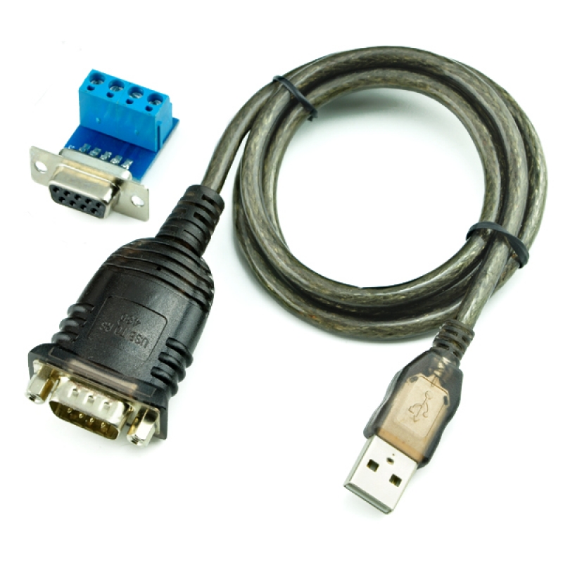
In the event you liked this short article and you desire to be given more info about rs485 cable i implore you to pay a visit to our web site.
- мқҙм „кёҖGiving Gambling As Gifts 24.05.30
- лӢӨмқҢкёҖImportance Of Furniture In Interior Decoration 24.05.30
лҢ“кёҖлӘ©лЎқ
л“ұлЎқлҗң лҢ“кёҖмқҙ м—ҶмҠөлӢҲлӢӨ.