Want to Know More About Rs485 Cable?
ьјўВЮ┤ВДђ ВаЋв│┤
ВъЉВё▒Въљ Sergio вїЊЖИђ 0Ж▒┤ ВА░ьџї 11ьџї ВъЉВё▒ВЮ╝ 24-07-01 05:40в│ИвгИ
Table 9-6 shows the connection diagram for a standard 9-pin serial cable. Table 9-6 Serial Cable Connections. In this case, cable connections must be made to Serial 1 at pins 5 and 6 of the 10-pin Serial Header or pins 7 and 8 on the 24-pin Field Header. We can gain insight into the operation of the RS232 protocol by examining the signal connections used for the primary serial port in Table 9 6. The transmit and receive data signals carry the messages being communicated between the QScreen Controller and the PC or terminal. By connecting pairs of these handshaking signals together, the terminal or PC can be made to think that the QScreen Controller is always ready to send and receive data. The QScreen Controller, however, does not implement hardware handshaking. If you do this now, remember to move the QScreen ControllerРђЎs serial connector back to Serial Port 1, and to change the terminalРђЎs baud rate back to 19200 baud using the "Comm" item under the terminalРђЎs "Settings" menu. Data translation between different machines can be performed with ease, and applications that communicate via the primary serial port can be debugged using the secondary channel.
Once you've installed it, you can go to the application. If you've already downloaded and installed the Software, rs485 cable go to the section called "Upgrading the Modules". If you have already downloaded the program, you are ready to go. The RS232 protocol provides for four handshaking signals called ready to send (RTS), clear to send (CTS), data set ready (DSR), and data terminal ready (DTR) to coordinate the transfer of information. Rather, it relies on software handshaking via transmission of XON/XOFF characters to coordinate data transfer and ensure that information is not lost when one of the communicating parties is busy. The secondary serial port is implemented by a software UART that controls two pins on PortA. On the other hand, the secondary serial port (Serial2) is implemented using hardware pins PA3 (input) and PA4 (output), and is controlled by the associated interrupts IC4/OC5 and OC4, respectively. We're assembling 2560 cards now, all IO pins broken out.

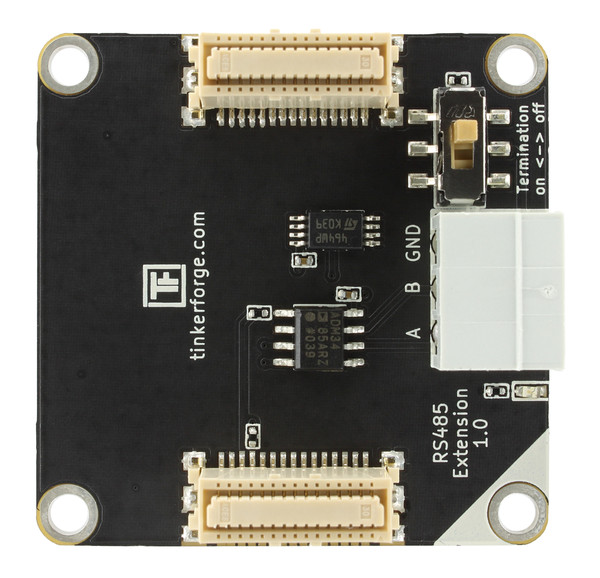
The board is a little bigger in length now, 77mm across by 73mm, has each header pins brought out to a 3.5mm pitch screw terminal, and to a pin in the 12x20 protoboard area. Easy to daisychain with In and Out headers. Out and other MAX7219 libraries will also work. Mini 2561 will be posted soon, we're waiting on stencil delivery to put one together. If more than one slave tried to drive the transmit line simultaneously, their serial drivers would fight with each other for control of the bus. To use a QScreen as a slave in a multi-drop network, simply define a word, (named Silence(void), for example) that when executed calls RS485Receive() to wait for any pending character transmission to complete, then disable the transmitter, and then execute a routine such as Key() to listen to the communications on the serial bus. When the keyword name is received by the Silence() routine running in the slave, the slave QScreen Controller executes RS485Transmit() to send an acknowledgment to the master (which should now be listening to the serial bus to accept the acknowledgment).
When the network master wants to talk to this particular slave, it outputs the slaveРђЎs ascii name onto the serial bus. The master and slave can then exchange data. You can use the QScreenРђЎs RS485 link to create such a multi-drop serial network. The QScreen Controller controls the RS485 transceiver with bit 5 of Port D of the processor. In summary, the code provided for implementing the second serial port is very flexible and can be used to support dual concurrent communications ports. For those of you interested in the details, hereРђЎs how it works: The low-level serial driver routines named Key(), AskKey() and Emit() are revectorable routines that can be redirected to use either of the serial ports. 12-digit, or 96 Bit, LED driver. Although the maximum standard baud rate of the primary serial port is 19200 baud, nonstandard baud rates of over 80 Kbaud can be attained by the 68HC11's on-chip UART and the onboard RS232 driver. Because the software UART is interrupt based, competing interrupts that prevent timely servicing of the Serial2 interrupts can cause communications errors on the secondary serial channel. ISS has a Tricaster LiveText data integration solution for diving using ISS MMS competition management software.
- ВЮ┤ВаёЖИђCours de Fran├Дais ├а Qu├Еbec : Explorez la Langue et la Culture Francophone 24.07.01
- вІцВЮїЖИђFive Killer Quora Answers To Under Desk Treadmill Uk 24.07.01
вїЊЖИђвфЕвАЮ
вЊ▒вАЮвљю вїЊЖИђВЮ┤ ВЌєВіхвІѕвІц.